Dairy effluent conveyance
The drainage and conveyance of dairy effluent requires careful planning to avoid pipe blockages. This is because dairy effluent is comprised of both liquid and solid material such as:
- manure
- straw
- gravel
- sand.
This is a starting point to consider when planning effluent conveyance under gravity and should be used in consultation with:
- an effluent system designer
- an irrigation specialist
- a plumber.
Pipe sizing and type
Dairy effluent can contain high levels of salt, so consideration should be given to the type of pipe that can withstand corrosion.
UPVC and HDPE (polyethylene) pipes are suitable for gravity or pressure pipelines. Rubber-ring-jointed PVC pipe should be installed in preference to solvent-welded pipe to avoid corrosion from the effluent.
If concrete pipes are used, sulphate-resistant cement is recommended with all exposed starter bars being galvanised to avoid decay. Steel cast iron and ductile iron pipes should be given a protective coating to avoid corrosion from the effluent.
For gravity pipelines, sewer-class pipes should be used rather than stormwater-class pipes. The main consideration for gravity conveyance is the presence of solids in the liquid. Table 1 gives recommended grade requirements of gravity pipelines with and without solids.
Table 1: Minimum grades for gravity pipe drains conveying effluent (Dairy Australia 2008)
Inside diameter (mm) | Minimum grade without solids | Minimum grade with solids |
|---|---|---|
75 | 0.2% (1:500) | 3.3 % (1:30) |
100 | 0.1% (1:1000) | 2.5 % (1:40) |
125 | 0.07% (1:1450) | 2.0% (1:50) |
150 | 0.05% (1:2000) | 1.7% (1:60) |
At least 150mm pipe is recommended for transferring effluent between ponds and for the outlet from ponds to the land application area or irrigation channel. Larger diameter pipes will have the advantage of higher discharge rates and less likelihood of blocking. Please consult with an irrigation specialist to determine the appropriate size pipe for your situation.
Pipe covering
Pipelines should be:
- buried at least 500 mm below the earth surface
- at least 600 mm below where there is vehicle movement.
The larger the pipe, the greater the cover required. If hydrants are used in conjunction with a mainline, hydrants should be protected from vehicle and cow traffic. Some farmers will install pine posts around the hydrants for protection.
Pipe positioning
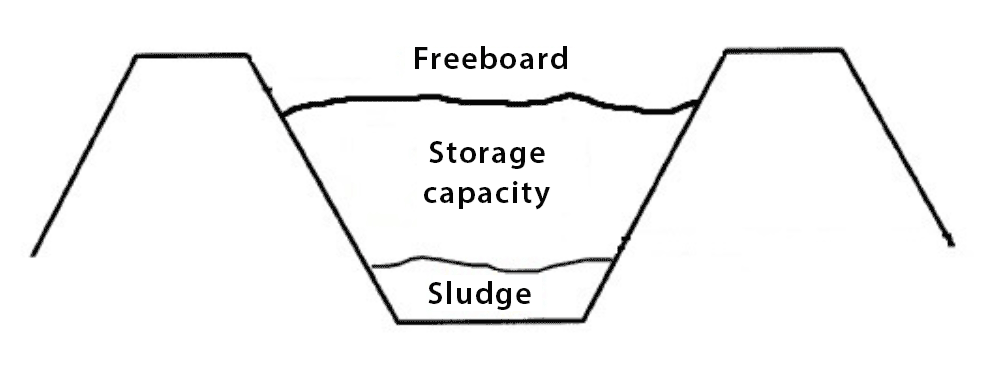
It is recommended that the outlet pipe or pump suction line are not within 0.5m of the bottom of pond. This will reduce the risk of sludge and solid material from blocking the pipes and pumps as per Figure 1.
Keeping floating solids in the first pond with a T-piece
 and second (storage) pond")
Over time, suspended manure solids and undigested feed will start to float on the surface of first pond. It is important that this material is retained in the pond, to improve the quality of the effluent passing into subsequent ponds.
The most effective way to prevent the floating crust from transferring into subsequent ponds is through the installation of ‘T-piece’, constructed from 250 mm diameter PVC. The T-piece prevents any floating solids from entering the storage pond, which can could block pumps and irrigators.
The vertical section of the T should extend at least 300 mm below the horizontal section of the T. The the top vertical section of the T should extend so it can be seen if the crust accumulates above the top of embankment height. The horizontal section should be installed at least 600 mm below the top of embankment height to provide a 600 mm freeboard (air space) on the ditch or pond (as per Figure 2 and Figure 3).

References
Dairy Australia 2008, Effluent and Manure Management Database for the Australian Dairy Industry, accessed on June 4 2021.
Managing Dairy Shed Wastes Technical Bulletin; Vol. 2, Dairy Research and Development Corporation 1994. Published by Department of Agriculture, Victoria.