Drip system maintenance and monitoring
Irrigation systems will only operate well if properly maintained. This is particularly relevant for drip irrigation systems as problems are not easy to identify before they become a problem, and emitting devices are very small compared to other irrigation methods, meaning blockages can more readily occur.
The most common problems with drip irrigation systems are emitter clogging, deterioration of dripper components or mismanagement of system pressures. Regular maintenance and monitoring are the best ways to identify and avoid problems before tree health and yield suffers.
Over time, system performance will decline to some degree in all drip systems regardless of management, but it is important to minimise this decline through maintenance and monitoring.
Systems that are regularly flushed, cleaned, have adequate filtration and are initially well designed should maintain an acceptable level of performance.
This factsheet outlines procedures and management techniques that all irrigators should use to gain and retain the maximum benefit from their drip irrigation system.
The three main areas described are:
- Flushing the system
- Cleaning the system (disinfestation)
- Monitoring system performance.
Flushing the system
Even with a good filtration system, blockages to drip systems can occur, and it is important to regularly flush mains, submains, and laterals.
Flushing these three components, in this order, is an important practice which generally doesn’t receive the attention it requires.
Depending on water quality, it is recommended to give the piped system a complete flush before the first irrigation of the season, several times during the season and again at the end of the season.
Monitoring the water quality during flushing will determine whether flushing is occurring frequently enough. As a guide, flush three times a season when irrigating with clean water and at least once every fourth irrigation with dirty water.
It is important to flush the system in the order of water flow (that is, main, then submains, and finally laterals).
- Flush the mainline while the submain and lateral flush valves are closed for at least 2 minutes or until water runs clean
- Close the mainline flush valve and start flushing the submains for at least 2 minutes or until the water runs clean (Figure 1).
- Close the flush valve of the sub-mains and flush the drip laterals patch by patch for at least 2 minutes until the water runs clean (Figure 2). Often two ‘slugs’ of sediment are observed in the laterals, the first will be sediment that accumulated at the end of the lateral, and the other from disturbed sediment along the base of the lateral.
- Close the laterals in consecutive order and check that all drippers are working.

Automatic flushing valves can be an option installed at the end of each lateral (Figure 3). These valves purge when the laterals are filling up at the start of each irrigation and may provide a suitable backflushing option if frequent flushing is required. Irrigators have had mixed results with this method of flushing, and it is recommended to regularly remove these valves and manually flush the laterals to ensure that an adequate flush has occurred.

The ends of laterals can also simply be bent over, or have a tap installed. Taps come in a range of designs (Figure 4).

Flushing manifolds (Figure 5) are popular as they make flushing easier and quicker, meaning flushing is more likely to regularly occur. As the importance of flushing gains awareness, greater attention to manifold design has occurred, ensuring manifolds are not too long, or the pipework under sized.
In some cases, existing flushing manifolds have been shortened or removed completely and individual taps installed, due to excessive drip line drainage and redistribution through the manifold. See Drip drainage for more information.

Industry standards state that a minimum flow velocity of 0.5 m/s is required to adequately flush lateral drip lines. This can be hard to achieve in poorly designed systems. Only a few laterals should be opened and flushed together to ensure sufficient water flows through the line. If the laterals are connected to a flushing manifold, open one at a time only.
If three-way taps exist on hydraulic valves (such as in Figure 6), switch the valve from auto to open after opening the ends of the laterals. This will bypass the valve pilot to produce greater pressures, resulting in a better scouring of the lines. Ensure that pressures do not exceed the maximum working pressure of the drip line, or fittings such as gromets.

Water velocity can be determined using measuring equipment or computer software. These methods require experience and can be time consuming. A simpler method is to measure the volume of lateral discharge that occurs during flushing, and with knowledge of the laterals internal diameter (ID), Table 1 can be used to determine if adequate velocity exists.

If the flow rate measured is significantly less than this, adequate flushing velocity is not being achieved. To correct this, reduce the number of individual laterals opened during flushing, or increase system pressures as previously described.
This exercise can be used to determine the maximum number of individual laterals that should be opened during flushing and form the basis of future flushing programs.
Cleaning the system (disinfestation)
Emitter blockages generally occur for two reasons – organic matter and mineral sediments. Each of these issues should be dealt with separately. Organic matter is commonly treated with an oxidising agent such as chlorine. Mineral deposits are treated with acid.
Organic matter can include algae, mussels, and biofilm. It is important to control organic matter as it increases the internal roughness of pipes, increasing friction loss throughout the system and resulting in lower operating pressure at the emitter, as well as potentially creating emitter blockages as growth moves into emitters.
Several products are now available which kill organic matter. The most common of these is chlorine, with hydrogen peroxide now increasingly being used. It is important to note when selecting a chemical product to use, read the label thoroughly prior to use. As many of these chemical products are not registered for the specific purpose of cleaning irrigation systems, this use is considered an off-label use in Victoria. For more information about using chemical products in an off-label manner, please visit the Agriculture Victoria website and search for off-label chemical use.
Chlorine is the traditional chemical used to kill organic matter which might have entered the system through the irrigation water or grown within the system.
The most common chlorine compounds used are sodium hypochlorite (liquid) and calcium hypochlorite (solid). Sodium hypochlorite (usually 12.5% chlorine) is easier to use and relatively safe compared with calcium hypochlorite (60% chlorine), which is explosive when placed in contact with ammonium fertilisers.
Chlorine is usually injected either intermittently or continuously.
Intermittent treatment involves periodic sterilisation, usually to prevent but also to correct a build-up of organic matter in the system. Information on injection concentrations can be found in the Preventative and Routine Maintenance Guide referenced at the end of this fact sheet. Injection should be at least once and as many as four times during the season depending on water quality. Between 0.5 and 2 ppm of free chlorine must be detectable at the end of the lateral furthest from the pump to be sure the whole system has been exposed to free chlorine. Swimming pool test strips can be used to detect free chlorine. The chlorination procedure described below should be used as a guide when developing a chlorination program that suits the grower’s drip irrigation system and management.
Continuous treatment involves injecting chlorine at every irrigation and should only be used if extreme algae or iron problems exist. Information on injection concentrations can be found in the Preventative and Routine Maintenance Guide referenced at the end of this fact sheet. A constant injection rate is adjusted so that one ppm of free chlorine is detectable at the end of the system. This method limits the flexibility of fertigation but is sometimes used when specific problems exist in the system. Check with your designer if you are considering this method. If continuous injection is required, hydrogen peroxide is usually the preferred chemical used today (see below).
Chlorination procedure
- Flush the system in the order of water flow (i.e. main, submains then laterals). Flushing before chlorination means that initially the chlorine does not have to act on so much organic matter within the system.
- Inject chlorine until it reaches the last dripper
- Run the pump for a further 10–15 minutes
- Shut the system down for 2–24 hours
- Flush the system again after chlorination, particularly if the chlorination was to correct the build-up of organic matter: note the sediment discharged
- Consider carrying out a system performance test (monitoring system performance) following chlorination.
Hints for safe and successful chlorination
Warning! Chlorine solutions are dangerous to human and animals; always wear proper protection for your eyes, hands, and body.
- Direct contact between chlorine and fertiliser can be explosive. Do not use a tank that has been used for fertiliser without thoroughly washing the tank. Contact between diluted chlorine and fertiliser is not hazardous but can reduce the efficiency of the chlorine
- Water travels about one metre every 3 seconds over whole drip systems. As a guide to determine how long it will take chlorine to reach the furthest point in the system, divide this distance in metres from the injection point by 20 to give the time in minutes
- To check the concentration of chlorine at the end of the lateral, use a swimming pool test kit. A common misconception is that chlorine can be detected at the end of a lateral by smell. Often chlorine is already on fingers or clothing, and this can give a misleading impression of its presence. In addition, the smell coming from the dripper might not be free chlorine, meaning that all the chlorine has been used (oxidised) before reaching the end of the lateral, and injection volumes have been underestimated
- When using chemical solutions in an irrigation system, a suitable backflow device is needed to prevent reversed flow to the water supply
- When having the system designed, consider whether chlorination is needed, including chlorinating large mains of low velocity
- Sodium hypochlorite does not store well. Purchase amounts needed in the short term only
- Many growers feel disappointed when flushing after chlorination if no sediment is found. As mentioned previously, chlorination should be viewed as a maintenance operation in most situations. Do not be concerned if little or no sediment is visible when flushing following chlorination.
Hydrogen peroxide is increasingly used to control organic matter in irrigation systems. It is stronger than chlorine and reacts faster, producing safer by-products (although some irrigators are finding chlorine still has an advantage when controlling particular issues, such as Bryozoans).
Hydrogen peroxide is a stronger oxidising agent than chlorine, with a greater rate of reaction and safer by-products (hydrogen and oxygen). It is available in various concentrations, with 35 or 50% usually recommended for irrigation. Unlike chlorine, it is effective at high pH and can be stored long term. Test strips are also available to determine the presence of residual hydrogen peroxide at the end of the system.
Like chlorine, it can be injected continuously at low dosage, or intermittently. Continuous low dosage is becoming popular.
Hydrogen peroxide is generally not recommended if asbestos cement or cement lined piping exists. Both chlorine and hydrogen peroxide have been known to cause corrosion at high concentrations near the point of injection. Not all pipework is suitable in this situation.
The same calculation method is used to determine how much chlorine or hydrogen peroxide to inject. It is important to inject the correct amount of chemical into a system. If too little is injected, the system will not be adequately cleaned. If the chemical rate is too high with either product, corrosion of low-grade stainless steel (such as that in solenoids) can occur. If chlorine is too high, rubber diaphragms in some PC drippers can harden over time.
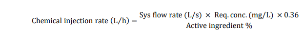
To calculate how much chemical to inject, determine the following:
- System (shift) flow rate (in L/s)
- Concentration of active ingredient of chemical being injected (%)
- Concentration of chemical required to be injected (mg/L)
Information on chemical injection rates can be found in the Preventative and Routine Maintenance Guide referenced at the end of this fact sheet.
Some agronomy services provide charts with various system flow rates and chemical concentrations used to provide recommended injection rates.
To deliver the total chemical required:
If the tank injects 500 L/h:
- Add hydrogen peroxide (from chemical injection rate calculation above)
- Fill the tank to 500 L
- Inject this solution for 1 hour.
- Determine that the chemical has reached the furthest point
- Leave in the system for at least one hour, but usually overnight
- Flush the system
Notes:
- The chemical volumes determined are injection rates (in L/h). If it takes two hours (for example) for water to reach the last dripper, the injecting rate will need to be doubled.
- For particularly dirty systems, flushing should occur prior to injection to allow chemical to work on less organic matter.
- If injecting into non-drain (ND) drippers, ensure adequate flushing occurs as dislodged material can enter emitters, partially leaving diaphragms open and causing emitters to leak
- If injecting downstream of media filters (See Injection point section below) add 0.5 - 1 L of chemical to each tank, depending on tank diameter, at least once per year, for periodical maintenance. Leave for several hours and backflush.
While either chlorine or hydrogen peroxide is used to manage organic deposits in drip systems, acids can be injected to control mineral deposits. Dissolved impurities in irrigation water, such as calcium and iron, can precipitate in the drip system. In regions using surface water supplies, this should generally not occur. If the water source is drainage or groundwater, or there has been an error in fertiliser mixing, acid injection can be necessary.
Chemical impurities can often be dissolved by lowering the pH of the water, usually by injecting dilute solutions of either hydrochloric, sulfuric, nitric, or phosphoric acid. Phosphoric and nitric acid have the added benefit of adding nutrient to the soil.
Warning! Acid should not be used if asbestos cement pipes are part of the irrigation system: acids harm the pipe wall and release fibres, leading to mass blockages.
Chemical injection can be hazardous, and irrigators can engage contractors to carry out acid and chlorine/hydrogen peroxide injections.
Steps for injecting acid
- Confirm that the system is suited to acid injection. Acid is corrosive to steel, aluminium, and asbestos cement. Nylon fittings are not resistant. Polyethylene and PVC are acid resistant.
- Flush the system in the order of water flow (main, submains, then laterals).
- Determine the system flow rate
- Test the maximum discharge of the injector pump with the irrigation system operating (for example, 1,000 L/h). Only use acid-resistant injector pumps.
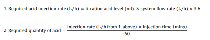
- Determine the concentration of acid required to reduce the water pH to the desired level.
To determine the amount of acid needed to decrease the pH, take a 1 L sample of the irrigation water. Add measured amounts of acid to this water and mix. Measure the water pH using a pH meter or test strips. Continue to add measured amounts until the desired water pH is reached, usually a pH of 2–4, depending on the nature of the blockage. To determine if this acid concentration will be effective, place an affected emitter into this solution. The mineral deposits should dissolve in 10–20 minutes.
This process is called an acid titration (Chart 1). The concentration of acid needed will depend on the initial pH of the irrigation water, and the type of acid being injected. Different acids have different concentrations. For example, hydrochloric acid is 33%, and phosphoric acid is 85%. Therefore, for the same water source, less phosphoric acid would be needed compared to hydrochloric acid, to reduce the water pH to the appropriate level.

- Start injecting acid with the irrigation system operating
- Continue injecting until the discharge at the furthest lateral has the required pH - check this with a pH meter or test strips
- Adjust the injection rate if necessary and repeat step 2
- Continue injecting for 10–15 minutes, then completely flush the acid from the system.
Always add acid to water, never water to acid
Injection point
Chlorine is historically injected downstream of filters, but more recently recommendations are to inject both chlorine or hydrogen peroxide upstream of the primary filter.
If injecting upstream of filters be aware of chemical loss when filters backflush. Controllers can be setup to avoid chemical injection during backflushing.
Acids are preferred to be injected downstream of all filter types to avoid corrosion. Some plastics are also not acid resistant. Fertilisers should also be injected downstream.
Monitoring system performance
Regular monitoring of a drip irrigation system is important to make sure it's working properly. This generally involves checking dripper discharge and operating pressure. Ideally this should occur as soon as the system is commissioned, and regularly over the life of the system.
For non-pressure compensated drippers (non-PC), the discharge stated by the manufacturer is a nominal discharge figure at a specific pressure (generally 100 kPa).
In a properly designed system, there will be less than 10% variation in dripper discharge throughout a valve unit (i.e. less than ±5% variation). This avoids having some plants under-watered and others over-watered.
Pressure compensated (PC) drippers discharge should also be regularly checked. If material lodges in a PC dripper leaving the diaphragm open, an increase in discharge can initially occur. Additional material can result in a reduction in discharge and eventually complete blockage.
For non-PC drippers, emitter operating pressures should be checked to ensure pressure variation is no greater than ±10%. This variation is less important for PC drippers, however, these should still be checked to ensure they are operating above a certain minimum and below a maximum pressure.
Regular testing of emitter discharges and operating pressures is important to determine if maintenance programs (such as hydrogen peroxide injection) are needed. A method for checking a drip system is described below.
- Pressure gauge and attachment (Figure 7)
- Measuring cylinder (Figure 8)
- watch
- Dripper recording sheet (see Table 2).

- Measure the pressure at the dripper using a pressure gauge and tapered attachment (Figure 7) towards the extremities of the submain and laterals in each valve (Figure 10). This usually means the corner of the block as well as the centre.
- Place a measuring cylinder (Figure 8) under drippers in the same locations described for pressure testing above. Make sure all the water from the dripper is being collected in the container
- Measure and record discharge for 36 seconds
- Convert the discharge into litres per hour (see Table 2)
- Calculate pressure and discharge variation (Table 3)
- Measure and record the pressure at the block control point if possible.

Drip line pressures can also be determined using a pressure gauge with a needle attachment, along with the permanent installation of pressure gauge nozzle adapters (also known as pressure take-off points). These come with either a barb for installation into dripper lines (Figure 9), or a thread for installation into PVC. Locations should be similar to that described above.

A variation in dripper discharge of more than ±5% and a pressure variation of greater than ±10% (unless using PC drippers) indicates that the system is either poorly designed, the control block pressure is incorrectly set, or some partial blockage problems exist.
Compare the results to the irrigation design specifications. Keep a record of the readings and compare them to future readings. This will help detect and correct any alteration in pressure and dripper discharge before crop damage occurs. Taking pressure and flow variation measures following system disinfestation is also highly recommended.
Carrying out this monitoring will help to minimise the decline in drip system performance.


This calculation is for field testing drip systems and should not be confused with the flow variation (FV) figures provided in many non-PC drip manufacturers' specification sheets. Flow variation as mentioned in specification sheets is used to determine maximum run lengths at the design stage. A different equation is used:

where Qmax = maximum flow rate and Qmin = minimum flow rate
Flow meters, both at the pump and installed in the lateral (Figure 11) can also be used to assess emitter performance. A flow meter at the pump will only provide an overall indication of changes to emitter flow rates, with further investigation needed to identify the location of this variation. In-line flow meters can be installed in laterals semi-permanently to determine specific flow variation along an individual lateral. Emitter number downstream of the flowmeter must be determined, and if a flushing manifold exists this must be isolated.
")
- Satellite and drone imagery can help identify poorly performing areas in orchards, which can be ground-truthed to determine if its irrigation related.
- Some mapping products can identify issues on individual rows and indicate a specific drip line lateral issue, which could be overwatering or underwatering.
- Some scheduling technology services provide drip line pressure monitoring at the same location as the scheduling technology, allowing managers to determine if water is reaching a particular lateral at an acceptable pressure.
Cutting and removing emitters for visual inspection periodically is highly recommended, providing irrigators with the opportunity to observe any emitter deterioration, and determine if maintenance programs are working adequately (Figure 12). Some manufacturers offer an emitter analysis service and inspection report.

More information
For more information contact Jeremy Giddings on jeremy.giddings@agriculture.vic.gov.au
Acknowledgements
Peter Henry, Agronomist, Netafim Australia
John Harvie, Mildura Irrigation
Trevor Sluggett, Agronomy Manager, Nutrien Water, Renmark SA
Further reading
Preventative and Routine Maintenance Guide
Netafim Australia Technical Library 2009